Before turning the power on to the instrument, there are several safety checks
that must be made.
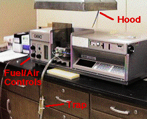
The hood must be on.
The trap must be full of liquid.
The flow controls for fuel and air must be off.
The acetylene tank must be either off or set to a safe operating pressure.
(See below.)
Wear your safety glasses!
|
|
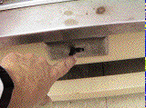
The
switch for the hood is located at the base of the walk-in hood to the left of
the instrument. Turn the hood on before doing any work with the instrument.
|
|
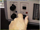
The
flow controls for fuel and air should be at their full clockwise (off)
position. These are needle valves, so turn them gently clockwise until you
feel them seat. Forcing them may cause damage to the valves.
|
|
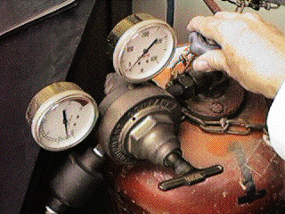
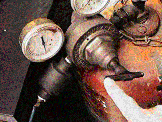
The
acetylene tank should have been left off by the last person to use it. Verify
this by noting that both gauges read zero. Verify that the main valve for the
tank is off by attempting to turn the tank valve to the right as shown.
|
|
Verify
that the pressure to the instrument is indeed set to zero by feeling the
regulator control. It should rotate loosely when in the zero pressure
position. Later on you will apply pressure to the system by turning this
control clockwise, but for now leave it in the "loose" zero pressure postition.
|
|
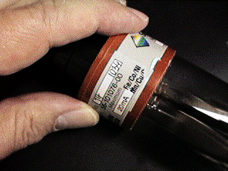
| Select
the type of lamp you will need for your analysis. The lamp shown is a
multi-element lamp, good for Fe, Co, Ni, Mn, Cu and Cr.
Also note the maximum operating current for the lamp. We generally will
operate at a current much lower than the 20 mA shown on the label to conserve
lamp life.
|
|
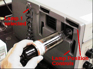
| The
lamp is inserted all the way into the lamp port. There are two sockets that
can be attached to the lamp. Note which one you have selected.
After we turn the instrument on, we will be able to use the two lamp position
controls to maximize the light sent through the instrument.
What looks like a second lamp port to the left is the permanently installed
background corrector lamp.
|
|
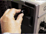
Be
sure the lamp is pushed all the way in.
|
|
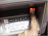
It
is now safe to turn the power on. The instrument should be allowed to warm up
for 20 minutes before critical measurements are made. You can proceed with the
set-up immediately, however.
|
|
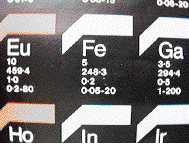
| There
is a chart on the wall to the right of the instrument that gives operating
parameters and information on the analysis you plan to do.
In this case:
Fe is the Element
5 is the lamp current in ma
248.3 is the wavelength in nm
0.2 is the recommended slit width in nm
0.05 - 20 is the recommended concentration range for this element in
mg/liter.
(Your results can be quite different from this concentration range, so be
prepared to change your standards after running them.)
|
|
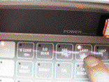
Send
power to the lamp by first pressing the Lamp Selection button. Be sure you
have selected the correct lamp.
|
|
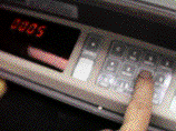
Use
the numeric keypad to enter the current. In this case 5 ma has been entered.
|
|
| Send
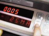
the 5 ma to the lamp by pressing the Read button.
The "25 ma" seen in the lower part of the display is just the instrument giving
you the possible range for input.
|
|
| If
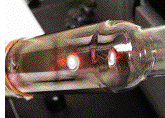
you aren't sure the correct lamp got turned on, take it out of the lamp port
and look at it. The orange glow tells you it is working properly.
Since these lamps give off UV radiation, do not point them directly into your
eyes.
|
|
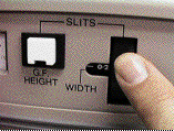
Set
the slit control to the value recommended on the chart. Here 0.2 nm has been
selected.
|
|
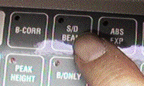
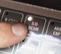
Turn
the instrument to single beam mode. The red indicator light on the S/D Beam
button should be off. Single Beam mode is required for the light throughput
optimization steps which follow.
|
|
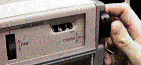
| Use
the coarse wavelength setting to move the monochromator to the wavelength of
the element line that was read ealier from the chart.
There is also a fine adjust that we will use to exactly position the
wavelength. Although the wavelength scale is fairly accurate, we cannot just
set it to the nominal wavelength. We will have to "tweak" the fine wavelength
control a bit until the energy response of the instrument is a maximum.
|
|
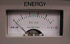
The
energy meter probably shows little or no response, even if the wavelength has
been set correctly. We must first tell the instrument to adjust the electronic
gain so we can see the signal. This is done with the EHT button.
|
|
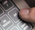
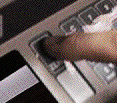
Press
the EHT button, then press Zero. This should move the energy meter to about
one-third of full scale.
|
|
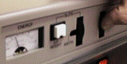
| Turn
the Fine Wavelength control until the energy meter shows a maximum reading. If
the meter goes off scale, repeat the EHT - Zero operation.
With the meter at a maximum you should be sitting directly over the analysis
wavelength.
|
|
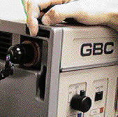
| Now
adjust the lamp positioning controls until the energy meter shows a maximum.
Use EHT-Zero to keep the meter on scale.
The light throughput should now be optimum. Do a final press of EHT - Zero for
best electronic gain.
|
|
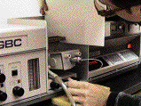
Put
a piece of white paper directly over the burner slot and look for the position
of the lamp beam. You must adjust the postion of the burner until the beam
goes directly over the slot.
|
|
The
burner positioning controls are located at the base of the burner assembly.
Adjust In-Out and burner Rotation until the beam is lined up along the entire
slot. Then ajust the burner height until the beam is about 1 cm above the slot.
|
|
Turn
the instrument to Double Beam Mode (red light is On). You are now ready to
light the flame and begin analyses.
|
|


